Man, what a year...we're seeing more and more projects based in BIM, and our staff continues to improve on their skill sets. Overall, despite the lingering tough economic conditions, we keep pushing forward and working to improve on the gains we've already made. Looking forward, next year should be an improvement, now that the election is past. But that doesn't mean we can go back to our older methods of producing projects.
We had a great conversation with one of water guys about BIM, and we talked about the issues we expose are not necessarily tool-based, but more design workflow based. CAD gave us a great ability to "hide" flaws in the design process, but BIM kicks the rock over and exposes all of the weakness you may have in a design. It's up to the project engineers and designers to get back to making sure their designs work first, and a 3D model really demonstrates this well. So next year will include more training for that level of employee, that will hopefully help alleviate fears about change, and keep them moving forward.
So here's my look back and look forward:
Autodesk University 2012 - this year, the crowd was really energized and wanting more. One of the general feelings I get now is that we can't rest on laurels from previous classes. Yikes - the students are on to us, and we (the instructors) really need to raise our game for next year. For the first time, it felt like the crowd had a better understanding of the basics of BIM, and fewer of the fears. The AU crowd's adoption of technology was very obvious. When I stepped out from behind a screen as Dr. Shots, about 50 iPads, tablets and cell phones popped up and started recording...I got a little "discombobulated" and almost cracked up...and yes, I promise to go slower in that class and cover a few less items (thanks for the feedback!). Nobody seemed to mind that they weren't any handouts - which is a great step for creating a more sustainable environment, as we used to kill quite a few trees every year...
One part that I left with mixed feelings about was the integration of shared data between BIM and other applications. There are a lot of new ventures out there, but it seems that we're only getting pieces, instead of the whole, big picture. At this stage in the development of BIM and other data-centric models, it seems that Autodesk would have a better idea of where they want this to go. We really need some focus to bring all the different pieces together, so that we're not all developing the same applications with different degrees of results. There are a lot of great new products, but some leadership from Autodesk on this other than talking about how we're all going to be in the cloud (without providing more specifics) would really be helpful at this point. Even in my own class, where the topic was about how we developed our own application to deal with linking data between applications, left me with more questions that answers. It will be interesting to see if they come up with a more uniform method for controlling the export and import of data - for example, the dbLink extension needs a lot of work (dynamic versus static, user control of what data is exported, etc.).
While there's lots of space at Mandalay, I'm personally glad we're going back to the Venetian - better quality of service, a more central location, which all lead to better attendance. Next year should really be a great event, and I can't wait. And yes - I'm already working on all NEW classes, with new material - keep doing the same thing and it gets stale quickly...
Changes in the Autodesk Sales Model - if you've ever been in a sales channel, you had to know this was coming. Web-based purchases, cloud-based software, annual versus perpetual licensing...all of these lead to the coming demise of the Autodesk reseller channel. Financially it doesn't make sense for Autodesk to keep supporting the channel, when in reality, we're no longer getting much out of them that bring additional value to the product sale. Support is direct with Autodesk through subscription, and most of the issues we have, the reseller can't fix since there either flaws in the program, or very simple " how do I..." questions. It's a bit sad, but savvy resellers should be looking to the add-in market, as well as the more refined services. Not every company can afford to have a BIM manager or developer on staff, so that market should be sustained...but it will have to be self-sustaining.
From the user perspective, the suites have been golden. They're still a bit pricey, but I'm using more of Inventor now than I ever have, and having a single version of Revit has been really nice. It makes the management of the tools much easier, but 50gb installations can be tough...hey, I'll wait. Next year, I'll be looking forward to upgrading to a more powerful system, so it will be interesting to see how the laptop versus tablet market is rolling along next fall.
Odds and ends:
-If you are in college, working on your engineering or architecture degree, take Revit classes - students with Revit experience or any 3D modeling experience are like gold to us.
- If you are a 30 CAD draftsperson, learn how to get up to speed in BIM AND Design - one without the other doesn't make for a very long term career outlook. Get at least a two year associates degree - that's better than nothing. If anything, really start looking at the post design market and tools. Applications like Navisworks still need solid users, and offering digital coordination/estimating/fabrication services is still not a bad idea.
- If you are a project manager or business owner, learn and understand BIM. Many people in the profession that haven't bought in to this are getting behind in the game. You've got to understand how this works and how it affects a project's bottom line. Stop hiding behind "how productive we are with plain AutoCAD"...with current trends showing BIM being more prevalent in the market that 2D now, all you're doing is kidding yourself.
- And if you are a facility owner, that hasn't starting requiring BIM as part of your deliverables, please step to the back of the bus...the rear door now opens automatically. Anyone had any validation or compliance issues lately, and had to deal with hundreds and thousands of paper documents, drawings, etc. with no real organization? Layer it - start with renovations, additions, and build your models over time, if you can't afford to get a good as-built modeled. It doesn't matter if it's AutoCAD Architecture/MEP, Revit, Bentley, ArchiCAD, or anything else. IFC is improving, and the next generation of users is going to wipe us all out if all we leave them is a stack of papers...go ahead...ask your kids...
For everyone, please enjoy the holidays. Spend some time with your family and friends - recent events have shown us that you can't take time for granted. Have a Merry Christmas and Happy New Year - we'll see you next year!
Take care - David B.
Tuesday, December 18, 2012
Tuesday, November 20, 2012
Revit 2013/AutoCAD MEP 2013 IFC Improvements
This post is part of an AU class this year, MP1465, Supercharge
Your AutoCAD® MEP 2013. It came up as we started working with outside vendors that are solid AutoCAD MEP users, but not Revit users - and that's what we're using.
First up, know the rules:
- Architecture and Structure items convert pretty nicely, with ACAD Arch walls converting to Revit walls. You may need to swap some styles, check justifications, etc. but getting the overall model works pretty well.
- MEP objects come into Revit from ACAD MEP as in-place families, but if you setup your import options, and have your classification definitions assigned to MEP objects in ACAD MEP, then they come in as "pipes, pipe fittings, duct, etc.". Be aware - they don't have the same behavior as a duct, pipe, etc. that was created with native Revit tools. But you can add connectors as needed to make these types of connections.
Here's the excerpt from the class (or as I like to call it, the "tease")...
IFC stands
for Industry Foundation Class, and it’s a file format that is universally
shared between CAD platforms. The intent is that an object in a program like
AutoCAD MEP can be converted into the same type of object in Revit, or other
BIM applications.
In order for an object to be exported to IFC, it has to have
an object classification assigned. To look at the default styles go to
ProgramData\Autodesk\MEP 2013\enu\Styles directory and open the IfcShareBldgElements (MEP).dwg file.

Once the items are selected, the classifications tab lists the information associated with an MEP
object that will be exported:

To use these in a file, and assign them to MEP objects, you
have to copy them into your current drawing. Use copy and paste in the style manager to add both classification
definitions to the current drawing.
Select OK to exit
the style manager. Now that they’re in the drawing, you can edit the properties
of objects to assign the classification. I’ll grab the ductwork, and then go to
the properties palette:

For most other parts, IFC
Type Classifications are mapped to MvPart
Objects (such as equipment, panels, and devices) automatically. This
classification is added in the Autodesk Catalog Editor by default. You can
modify this classification or add more classifications to the content library
in the Autodesk Catalog Editor.
Once
you’ve added the correct classifications to MEP objects, review the IFC export settings. From the
application menu, select the Export
tool, and then select IFC. The
options are located on the export dialog, and the object tab lists all objects that loaded into a drawing
– you can choose to add or remove objects as needed.
After you review the options, you can run the export. The
IFC file is created in the project folder. To test this, I’m going to open the
file in Revit. Before doing this, open the IFC
Import options on the Application
menu, under Open:

Before importing an IFC file, you need to go through and map IFC class names to Categories and sub-categories. This tells the MEP object what is used to control
its display in Revit.
Once the IFC file is imported, it will appear something like
this:

The imported objects take on most of the characteristics of
the equivalent objects in Revit. You may need to check IFC mappings in both the
AutoCAD MEP file and the Revit file during this process, but this represents a
major leap in compatibility between the applications.
Be aware that imported objects may not completely take on
the behavior of a normal duct. For example, the duct is treat like a duct with
properties assigned, but it does not include the connection, system or sizing
behavior. You have to add a connector to attach duct to it.
I don’t care what anybody says…this is really cool…
Happy BIM'ing - see you in Vegas!
zzzz....uh...huh? AU is in a week? Geez, I overslept..
Wow, where does the time go? Autodesk University (#au2012) starts classes one week from today...and the last couple of months have been crazy, getting all of the handouts, datasets, powerpoints, props, home movies, etc. finished. But I'm about there...
And when you finally get a moment to reflect, you hope you've put something together that really hits home with users. This year's approach was a little different - I wanted to find what the really obscure little things were that come up as support issues, and get them addressed. But I also needed to hit on the bigger picture, and make sure that the day to day items - using systems, making families quickly from scratch, or from manufacturer's content, etc.
And then I an email from an engineer I know, saying that he doesn't think MEP BIM is ready for primetime yet. And I couldn't disagree more, but if you don't train your staff for a few years, then, yeah - you're likely to have the same attitude. So here's what I think - Revit MEP 2013 and AutoCAD MEP 2013 represent the best two MEP design applications on the market, hands down. Both have their strengths, but both require you to make some changes to your design process.
Here's an example. In one of my classes, we talk about adding an instrument connection to a duct or pipe. The instinct says, add a tap. Instead, if we're making this connection at a fitting, such as a duct tee or flowmeter, why not add the physical connection to that component? It will stay connected to the part, if the part moves or changes size, the connection is still there. It can be fabricated into the part prior to being added in the field, so that may save a little "field fit and finish" time.
That's one of the challenges that comes with BIM. If you're still in the drafting mentality, then all you're thinking about is a line or circle - but in BIM, you HAVE to think more from a DESIGN standpoint. It's all about making a more easily constructable building, that's more sustainable while allowing for creativity in the design.
The beauty of AU is that it's a gathering of like minds, that are looking for that tip, or method, that helps you stay current with technology, or gain that competitive advantage. We're driven to find better ways to leverage our tools, and make life easier for ourselves (as though it isn't already). And we really want to find ways to interconnect all of this information, and come up with the big picture, that satisfies the client's and end users needs (think airport electrical outlets).
So take a little time this week - network with your peers, get to know some of the industry leaders, and take advantage of some of the best and most passionate instructors in the world. We'll all be hanging out in the same place - so come by, say hello, and let's talk about the future. And if you can't make it, check our AU Virtual - last year, tens of thousands did - so the learning doesn't stop on November 30th. I'm ready - are you?
See you in Vegas!
Sunday, September 16, 2012
'Peat and Repeat....Additional Revit Labs coming soon for AU 2012
Looks like my two Revit MEP labs will be repeated, due to demand. If you tried to get into either one of these sessions, but couldn't, check back this week. I've approved them being added, and are just working on the details for the time and location with the AU event staff...so stay tuned!
Class ID: MP1477-L - REPEAT is MP6895-L!
Class Title: FASTER Families for Revit MEP!
Class Type: Hands-on Lab - Wednesday 1:00p
Class ID: MP1478-L - REPEAT is MP6889-L
Class Title: Perfecting the System for the Revit MEP Project
Class Type: Hands-on Lab - Tuesday 10:30am
Anybody got a throat lozenge I can borrow....?
thanks - David B.
Thursday, September 13, 2012
Revit MEP Circuiting tips...poles or phase?
Ran into this one recently...we have a project with a new user that is adding devices to circuits. In the project she's working on, we have number of poles and voltage assigned as a parameter, but somewhere along the line added a phase parameter that was also equal to the number of poles...which, if you're the electrical designer, you know is wrong.
So here's my simple explanation, with a little help and clarification from my buddy Dan Stine...the Number of Poles in a circuit relate to the physical slot locations on a panel. The Phase refers to the A/B/C branches of a panel. Phase is a product of typical AC (or alternating current). Without going into great detail, know that Revit support single phase (panels with A/B branches, just like your house) or 3 phase (A/B/C - most commercial applications).
With electrical connections, you'll have these types of connections:
120/240 - these are single phase panels, with two poles - most commonly found in residential
120/208 - a three phase panel, more common in commercial applications. This type of panel also requires 4 wires to use all three slot sizes, from 1-3. In some cases, a 120/208 single phase connection can also be used - for example, in a apartment building.
120V is common in the US, but not common in other areas, such as Europe.
120V - A single phase, single pole Circuit - unless it's a GFI circuit, which could be single pole but 2 phase
208V/240V - typically a 2 pole, 1 phase circuit, but also could be three phase (for example, in the event of a 208V GFI Circuit). 208 volt or 240 volt systems can both be either single phase 2 pole, or 3 phase 3 pole circuits.
Higher voltage panels for commercial and industrial applications are typically 277/480, indicating a one to three pole circuits. 277 volt circuits are almost always single phase, single pole, while most 460-480 volt circuits are 3 phase circuits. Depending on the power requirements, you can have 480 volt, single phase, 2 pole circuits - so make sure you check for this when specifyign your equipment.
In my simple little, non-electrical mind, it's a bit confusing, but from Revit, it's pretty straight forward.
If something is 120v, set the number of poles to 1. This will take up one slot in the panel, or one "circuit"
If something is 277v, set the number of poles to 1. The phase will also be set to one. For 208v/240v circuits, these can be single phase 2 pole, or three phase, 3 pole.
For 480V, in most cases, the number of poles will be 3. a 3 pole circuit takes up three slots, and can only be used in a panel that is defined as a 3 or 4 wire, 3 phase panel. You can have some systems, such as electric heat, use a 480v single phase, 1 pole circuit - again, check with your vendor before defining the circuit.
These are all set under electrical settings, for the distribution systems:
 Revit requires that the proper combination of poles and voltage in order to add something to a circuit. There are two configurations for any type of a three phase panel - Delta, which doesn't include a neutral branch, and Wye, which does include a neutral.
Revit only recognizes single or three phase systems when you define your distribution system. For example, you might have a device or circuit, that requires 208v service but is single phase - you still have to assign the number of poles to 2. Otherwise, it can't be connected to a panel.
For more information, talk to a more reliable source than me - your local electrical engineer.
Hope this helps - if anyone wants to add to the conversation, knock yourself out!
thanks - David B.
Tuesday, August 28, 2012
A few shameless plugs...for AU 2012!
I gotta love our marketing people...they've really been grabbing on to social media and getting ourselves known for being thought leaders in the BIM arena.
So they put together a little highlight reel for the classes I'm teaching at AU this year, showing a few of the projects we've worked on in Revit, along with a few pics from previous classes...check it out!
Class ID: MP1478-L
Class Title: Perfecting the System for the Revit MEP Project
Wednesday - 8:00am
And you thought I was a geek...see you in Vegas!
later - David B.
So they put together a little highlight reel for the classes I'm teaching at AU this year, showing a few of the projects we've worked on in Revit, along with a few pics from previous classes...check it out!
Here's the list of classes I'm doing this year - in case you missed it:
Class ID: MP1414
Class Title: Revit MEP 2013 - On Steroids!
Wednesday - 10:00am
Class Title: Revit MEP 2013 - On Steroids!
Wednesday - 10:00am
Class ID: MP1461
Class Title: You did WHAT? Revit MEP and AutoCAD P&ID? Amazing!
Thursday 1:00pm
Class Title: You did WHAT? Revit MEP and AutoCAD P&ID? Amazing!
Thursday 1:00pm
PS - for the class above, I'm really excited about this one - we're doing stuff that everybody says we shouldn't be doing - but it's not just about the programming. It's about how we went through the decision and planning process, to come up with a solution that was cost effective for the company while giving us a competitive advantage in our market.
Class ID: MP1465-L
Class Title: Fast Content for AutoCAD MEP 2013
Tuesday - 5:30pm
Class Title: Fast Content for AutoCAD MEP 2013
Tuesday - 5:30pm
Class ID: MP1470
Class Title: Supercharge your AutoCAD MEP 2013!
Thursday - 10:00am
Class Title: Supercharge your AutoCAD MEP 2013!
Thursday - 10:00am
Class ID: MP1477-L
Class Title: FASTER Families for Revit MEP!
Thursday - 5:00pm
Class Title: FASTER Families for Revit MEP!
Thursday - 5:00pm
Class ID: MP1478-L
Class Title: Perfecting the System for the Revit MEP Project
Wednesday - 8:00am
And you thought I was a geek...see you in Vegas!
later - David B.
Wednesday, August 22, 2012
Fixing Acute Angle Pipe Deflection and other Piping Errors in Revit MEP
This tip comes straight from the top, from my buddy Dave Pothier...even though he's management now, he's still a geek at heart - gotta love it...
We had a recurring couple of problems with fittings we had defined for Ductile Iron pipe. When Autodesk brought their new versions out a short while ago for the AWWA standards, we were still having some issues, so we had a chat with Dave about it.
Problem 1 - some fittings at angles like 45 degrees could not be created, and we kept getting a "line too short" error - even though you could set the angle in the family, and it would work fine. As it turns out, my techs were modeling an existing plant on a project. To keep from getting crazy plant dimensions, they did what any good CAD tech would do - they set the units to 1/2" and 1".
Then we sailed in trying to place fittings that were accurate down to 1/16" - so when these fittings would try to fit under the higher scale, they couldn't be placed. We changed the project units down to 1/32" and everything works again. Go figure...
Problem 2 - this one was a doozy, and we had a lot of back and forth about it. When we finally did a web session with Autodesk, we were explaining how mechanical joint pipe connections have to be able to flex up to 5 degrees (2.5 each way) around a fitting, since all of this work is buried underground (and gasp, dirt does move). We also had ongoing problems where we could get pipe to deflect at angles great than 90 degrees (since the fitting angles were all between 0-90) but not at acute angles (when the deflection needed to occur, since these fittings don't exist as standard). Their fittings weren't doing deflecting, but then Dave noticed how we had the pipe connector set on the fitting. Here's part of his response:
Once you do that, you can turn
On the Allow Slope Adjustments check box. After turning it on, set the System
Classification back to Fitting. Do that for both connectors.
Now we when make the connection, we get piping deflecting the right way:
 Sometimes it's just the simplest things - but thanks again to Autodesk for helping us out, and really get the most from this great package! I'll make sure we get this into the Revit MEP lab I'm teaching at AU, so you can see how do fix this first hand.
Have a great evening! David B.
We had a recurring couple of problems with fittings we had defined for Ductile Iron pipe. When Autodesk brought their new versions out a short while ago for the AWWA standards, we were still having some issues, so we had a chat with Dave about it.
Problem 1 - some fittings at angles like 45 degrees could not be created, and we kept getting a "line too short" error - even though you could set the angle in the family, and it would work fine. As it turns out, my techs were modeling an existing plant on a project. To keep from getting crazy plant dimensions, they did what any good CAD tech would do - they set the units to 1/2" and 1".
Then we sailed in trying to place fittings that were accurate down to 1/16" - so when these fittings would try to fit under the higher scale, they couldn't be placed. We changed the project units down to 1/32" and everything works again. Go figure...
Problem 2 - this one was a doozy, and we had a lot of back and forth about it. When we finally did a web session with Autodesk, we were explaining how mechanical joint pipe connections have to be able to flex up to 5 degrees (2.5 each way) around a fitting, since all of this work is buried underground (and gasp, dirt does move). We also had ongoing problems where we could get pipe to deflect at angles great than 90 degrees (since the fitting angles were all between 0-90) but not at acute angles (when the deflection needed to occur, since these fittings don't exist as standard). Their fittings weren't doing deflecting, but then Dave noticed how we had the pipe connector set on the fitting. Here's part of his response:
"...Select the (pipe) connectors and
temporarily change the system classification from “Fitting” to “Global”
Now the fitting should allow the
pipe to deflect without the fitting’s angle adjusting. I’m not sure how great
of an angle you can have but it should work for what you are doing. Let me know
if this works for you."
Now we when make the connection, we get piping deflecting the right way:

Have a great evening! David B.
AutoCAD P&ID - A couple of quick tips...
We're going whole-hog (for those folks not from the South, this means that we are ardently pursuing a course of action - it just takes a lot less typing to say it) into AutoCAD P&ID, and really gaining the benefits over the old-school lisp and vanilla AutoCAD methods we used before.
But like any other Autodesk application, you've got to follow some rules. Here's a couple of tips that will help with some of the errors.
Off-page connectors - Autodesk released a fix for these not too long ago, but there's a better way to screw this up. If your pipe line segments between the connected drawings are not the same type - for example, you used the Primary Line Segment in one drawing, and then used Secondary Line Segment in the other drawing, where you wanted to make a connection - you won't get the tag properly labeled. We did this with several lines, just not paying attention. Off page connectors require the same line segment type to properly connect, so check this in both drawings before you implode.
The other good one relates to Validation. We've been using the Validate tools on P&ID objects, but we also place all of our geometry in paper space - since we're not working at scale. If you configure the Validate tools to check for Base AutoCAD objects, you might not get anything to show up as an error - even if you've added all kinds of cheatin' shortcuts.
The Base AutoCAD Objects check only looks at model space - so if you are importing old P&ID's to convert to intelligent objects, do your work in Model space, and then check. You'll find all of your random linework and be able to edit them right out of your shiny new diagram.
I've got more, but fixing all this has made me tired...time for a nap...
Later - David B.
Thursday, August 2, 2012
Drawing Yard Piping in Revit MEP
In some projects, you might want to add the piping that connects between buildings and structures as Revit pipe instead of Civil 3D. I do this when I'm trying to maintain a connected system that doesn't go out beyond a campus, or scope of a project.
It can get a little tricky, so here's a few tips. First, make sure you have your site file linked in to your view. You need that as a point of reference. In our case, we have a project that is based on shared coordinates (site is linked center to center, then we acquired the coordinates from the site file to line our project up to those coordinates).
Next, get your levels added. You can either work from an overall relative level elevation of 0, which we do include on some of our projects. When you have this level in your project, you can use the actual invert elevations from the existing or proposed pipe.
If not, you need to do a little math - for example, you have a level defined at 303'. The pipe invert is 322.43'. You need to do the math, subtracting the level from the true invert, so our pipe is at 19.43'. You don't need to do any conversion if your project is in feet and inches instead of decimal feet - typing this value in will do the conversion for you.
You also need to know if the invert elevation is to the top, middle or bottom of pipe. That will come in handy as you start to draw the pipe.
Next up - calculating slope. This is why I decided to add this post - for the life of me, I couldn't do the basic math to convert slope to inches, so being the geek I am, I did a Google search and found a great table from a book called Basic Engineering for Builders, written by Max Schwartz. Here's the conversion table:

Before you add the pipe make sure you have the right fittings, such as the ductile iron mechanical joint library. We use a modified version of an old CADWorks library based on Clow for ours, but make sure your outside diameters are correct.
Now you're ready to add the pipe. From the home tab, select the Pipe command. Set the size and invert elevation for the offset, after doing the math. Next, select Justification to bottom, middle or top based on what you have as you invert elevation.
If the pipe is sloped, make sure you turn slope on. The direction you're drawing determines whether you use slope up or slope down. If you're starting from the highpoint, select slope down. Set the slope to the right value - if the values you were given were based on percentage, use the table to find the inch to 12 inch value (re: .5% = 1/16"/12" slope).
After you review this, pick your second point. And this is where the fun begins. Sometimes, Revit doesn't want to add a right angle to the pipe, especially if the view is not at right angles. What you want to do, when this happens, is rotate your view based on a pipe segment. Make sure your view crop region is turned on.
Select the crop region, and then pick the Rotate tool from the Modify tab. The center of rotation will show up in the middle of the view. Move your mouse over the center, pick it and drag it to the end of your pipe. After you've moved the center, you can rotate the view around this point. You can either pick a line that is orthographic first, then the center line of the pipe. That usually works, but sometimes you have to pick the first line for the rotation as the centerline of the pipe, then pick an orthographic line relative to your view. Either way, get the pipe in view flat.
Once it's flat, the fittings should work as designed. If you want to see this solution live, then join me at Autodesk University this year in Las Vegas, for my class, Revit MEP - On Steroids. We're going to have a lot of stuff revolving around site based projects in that class. If you can't make it to AU, it will be available after the event if you're signed up as an AU member. You'll have a handout with pretty pictures, and they may even have a recording of the class.
Hope this helps - happy BIM'ing...David B.
Thursday, July 19, 2012
Hitting Benchmarks...and a great read...
Happy to announce we just passed 100,000 hits on the blog - I'm sure it's not as prolific as other sites, but hopefully in all the hits, I've added information and tips that have helped people out. So for all the people who hit this site and found information that was helpful, thanks for dropping by and tuning in. For all those who hit it by accident, maybe you learned a few things about what me and my geek friends really care about.
Speaking of caring about stuff, I just finished reading the AUGI "BIM is a Tool" article -
Speaking of caring about stuff, I just finished reading the AUGI "BIM is a Tool" article -
http://www.augi.com/library/bim-vs-communication - written by Damon Socha and Jennifer Lanzetti. They couldn't have been more right - it doesn't matter how cool or efficient the tool is if you can't communicate your design intent clearly. The one thing I'd add is that BIM tools do help you find the issues more clearly than in traditional 2D documentation process. It's all about the quality of the response - do you take advantage of the information, and use it to make a better design, reduce conflicts and improve quality.
One other thing - registration for AU members for Autodesk University starts August 28th - if you're planning on attending, and aren't currently a member of the site, go ahead and get signed up. That way, you're more likely to get into the venue's hotel (Mandalay Bay) and get better rooms. You'll also get a better pick of the classes. If you're a first timer, look me up - I'm planning on being one of the mentors for newbies this year.
Have a great day! David B.
Wednesday, July 11, 2012
Autodesk Fabrication - Yikes!
Now this I can't wait to see - Autodesk has released Autodesk Fabrication, a set of tools that works with Revit MEP models. You start with a Revit model including pipe, duct, etc. Export the model to a .RIF file, and import it into FABmep.
Fabrication lets you break the model down into modular systems, spools, etc. I noticed it contains libraries for pipe from Victaulic for fittings - but I'm real curious to see if the covered any others, like Charlotte or ACIPCO ductile iron...if they did, I'm really keen on looking into this.
Check it out at www.autodesk.com, and then search for Autodesk Fabrication - a free trial is available.
thanks - David B.
Wednesday, June 27, 2012
Small Groups, Large Groups, Red Crowd, Blue Crowd… AU Conference Presentation and Teaching Tips
Now that I know I’m headed back to Las Vegas for Autodesk University this year, it’s
time to pass off some ideas about how to have a successful class. Whether you’re
a first timer or an old dawg, you’ve got to understand that presenting at a
conference isn’t the same as a regular training class, or presenting to your
buddies in the office. So let’s start with a few things that help your classes
get high marks.
1. Know Your Audience
If you’re a beginner, intermediate or advanced instructor,
this is the most common mistake. Don’t teach symbiotic quantum physics to first
year AutoCAD users…and it may sound silly, but keep it simple. You’re not there
to impress them with your prowess or command of the English language. You’re
there to communicate ideas, instill excitement and passion, and motivate the
learner.
The AU crowd, for example is a little different. They’re a
highly technical bunch, but they also are in Vegas…yes, Vegas has them now. And
in most cases, they have a fairly good understanding of how the tools they’re
using work, but are looking for the gems and tips they can’t find in the books
or help file. When they signed up for classes, they were looking at your description
and skill levels. So whatever you’re teaching, you need to stay in that general
playground.
The key is to make sure your topic is something that is
valuable to them. Cruise the discussion groups, talk to coworkers and check out
the blogs to see what people are looking for. Since you’ve already submitted
your class, make sure you tune it as needed so the information is relevant. Even
if it’s advanced class, you’ll always get a few lost souls that probably didn’t
mean to sign up for your class, but could really benefit from the topic.
If you’re presenting for a first time, it can be daunting. I
was so nervous in my first AU class, I kept tripping over the screen stand
legs, which unfortunately stuck out about 3 feet in front of the screen
(appropriately the class was about interference conditions in AutoCAD MEP). Get
out and literally get to know your audience. If all you do is stand in front of
the podium, your first contact occurs when you begin to speak. I like to walk
around the room, introduce myself, talk to the users, even meet some outside
the door (I’ve also been known to take tickets and charge admission…oops, probably
shouldn't have said that). Ever notice how it’s easier to talk to friends than a
large crowd?
This requires that you make sure you get into your
presentation earlier, so have everything setup and ready to go well before the
presentation. Make sure the software is open to files you’re using, your
presentation is loaded. If you’re speaking at an event where there’s dinner or
lunch being served, don’t sit by yourself – or even with friends. Sit at a
table with people you don’t know and at least introduce yourself. You’ll find
it’s easier to connect with people before the presentation than during.
2. Preparation - Practice, Practice, Practice,
Practice, etc.
There’s a big difference between knowing something and
owning something. As much as I present, even the same things, it’s still a good
idea to go through the presentation – night before, etc. I used a short script
prompter, which contains the key points and sections. I leave it on the table
where my laptop is, if I’m driving, since this helps me stay on course. But no script keeps you from flubbing if you
haven’t gone through everything. I had updated my computer before AU, but didn’t run
through the steps in the exercise – my path to the lookup tables for pipe fittings in Revit was wrong…boom –
but we turned it into a teaching moment, and showed the class why it broke.
That’s rare, but sometimes you have to make quick adjustments. Try standing in
front of the mirror – watch your facial expressions, hand movement, body
posture – but nothing exudes confidence like owning the material. And never,
ever, ever rewrite material the night
before. Make sure you deliver exactly what you say you’re going to deliver –
set the right expectation for the class.
3. Relevant Topics – Stay on them.
As much as you may want to teach lisp programming that sets
layers to an Architecture crowd at AU, that may not be what the crowd is really
interested in. Find something that’s current and fresh – don’t dwell on how you
did things in the past, unless you’re using it to define context. For example,
a great expression is “I used to do this way, but then I learned a better way”.
And always
credit the person who taught you – it shows humility, and respect.
4. Presentation is everything!
At Bobby Flay’s Mesa Grill, in the Bellagio hotel, it’s all
about presentation – getting the fries to be fluffed up a specific way so they
look enticing. A former co-worker of
mine, David Garrigus, was a big inspiration – the ball and chain demo on ACAD
2000 was one of the best. You may have a style, but you can’t rest on it. You
can keep the style, but change it up – do something different at every event. I
may have fishing videos before the class, but every year I bring different
props.
One of the things that drives me nuts is a presenter who
hides behind a podium or desk, and doesn’t stop and step out. Engaging the
audience is mission critical at an event like AU. You want them to share how
you feel about what you’re teaching, but say it a little gently.
We even did the dating game once – but I won’t ever do it
again. Judge the response – if it works, tweak it. If it doesn’t, run away from
it. Don’t be afraid to ask people what they think – but also don’t be depressed
if your presentation gets trashed by one or two people. There’s always a critic
that thinks they can do better, or wants a specific presentation. Most
important – be yourself.
5. What to do when Things Break Down – and They
Will!
Beware
– if some disagrees with you, and they will, never trash them or their idea. Say
something like, “I hadn’t thought of that, but it sounds interesting.” Many
times, and unfortunately, there will be someone in the group that wants to
bring you down a notch. Don’t ever play into it – better yet, try to deal with
it after the class, and stay on track, so you can finish what you need to
cover.
If
something crashes, don’t dwell on it – even in a lab, you can still step out,
and talk about what you’re trying to accomplish. One of the things I do is keep
presentation or lab files saved at critical points, so a user can pick up and
keep moving if they get behind, or worse, if something breaks.
And
I’m a little superstitious – I always bring two laptops with me, just in case.
But Autodesk is great about providing powerful desktop systems that you can
use. One of the reasons I get to AU on Sundays is so I can spend time in my
labs on Monday, and make sure all of the datasets are current and correct. I
don’t recommend trying to customize the AutoCAD or other software on these
computers, as not everyone who teaches will share your ideas about how menus
suck and keyboard shortcuts are the only way to go. That’s when the dual laptop
method works best. All it takes is a little static – and you’re talking about
your kids for the next 75 minutes… and getting a crappy score.
To
wrap it up, understand that AU is not a traditional training event, so you can’t
approach it with the chalk and talk method. Be creative – engage the audience –
know your subject – but most of all, have a great time and enjoy the privilege.
Not everyone is crazy…excuse me, qualified
enough to teach at AU, so make the most of it!
Later - David B.
AU 2012 - Time to get loaded up!
You'd think I would have learned by now, don't offer to do too much...but if it wasn't so much fun...
For AU 2012, held at Mandalay Bay in Las Vegas this year, November 27-29, 2012 (au.autodesk.com), I've got six classes:
Class ID: MP1414
Class Title: Revit MEP 2013 - On Steroids!
Class Type: Lecture
Class ID: MP1461
Class Title: You did WHAT? Revit MEP and AutoCAD PID? Amazing!
Class Type: Lecture
Class ID: MP1465-L
Class Title: Fast Content for AutoCAD MEP 2013
Class Type: Hands-on Lab
Class ID: MP1470
Class Title: Supercharge your AutoCAD MEP 2013!
Class Type: Lecture
Class ID: MP1477-L
Class Title: FASTER Families for Revit MEP!
Class Type: Hands-on Lab
Class ID: MP1478-L
Class Title: Perfecting the System for the Revit MEP Project
Class Type: Hands-on Lab
Usually the labs fill up first, so make sure you sign up early. I'm also volunteering to be a mentor to newbies and first timers, so I'll be in Vegas on Sunday, November 25 around midday.
Registration starts in early August, so if you haven't created an AU account, get online and do it today - it's going to be a blast this year!
Later - David B.
Wednesday, June 20, 2012
Piping, Worksets and Large Projects in Revit
Came across a little tidbit about changing connected systems (in this case, piping) on a good sized project. It appears that if you have worksets defined by building or structure, and you have connected geometry that is in more than one workset, you need to make sure that you're the owner of all worksets the connected pipe or duct belongs to.
In our case, we've set up an overall site model, that contains worksets based on building and discipline. We had a group of pipe we needed to shift down about a foot. When the tech went to move the pipe, he got an ownership warning (along with the editing request). In this case, the pipe that was being stretched was connected to a pipe in another workset the tech didn't have enabled, so the command fails. enabling the workset eliminated the dialog and allowed the move, even though the pipe being edited wasn't in the disabled workset.
We've discussed doing workset by systems, but this seems to be a little more trouble...so let me know how you're dealing with it - is it better to have a system that's connect across a longer distance in one workset, or do it all by building? (By they way, we also have the yard piping in its own workset, too.)
Ain't this BIM stuff fun...later - dab
Wednesday, May 30, 2012
Are you getting SPIKES in BIM?
I'm noticing an interesting phenomenon. As we make our move to the BIM environment, we've learned that everything moves forward in stages. Obviously, different people learn at different rates. We have users that have easily adapted, and are constantly pushing the envelope. For users that are new to BIM, we keep coming across the "hesitant" user.
You can easily identify these folks. At the pool, they start by only getting in up to their ankles...and quickly get out because the water temp isn't exactly warm enough (others simply pee in the pool in vain attempt to warm it up). I always wind up behind this person in line at Starbucks in any airport...standing there, staring at the screen, wondering if the expresso will keep them awake on the flight, or if the protein in the smoothie will make them constipated for days.
Anyway, back to the projects. We've had some weird issues show up. And by the way - this isn't happening just for us, but across the spectrum of design firms, so my examples are global. For example, we have several structures to renovate and build from scratch, but the project manager only chooses to use BIM on the new facilities. Not that there's anything wrong with that, except that we're connecting equipment between the facilities - so it would have been really nice, and incredibly more efficient in the design process if everything new was created as BIM objects.
I've also heard about other projects, where the client wants AutoCAD, wants 2D, isn't interested in 3D...but the question is asked about using laser scanning and point clouds to generate an as-built, for presentation purposes, then runnin' back home to Mama and delivering plain AutoCAD.
It seems that every once in a while, an old school team leader hears about BIM - and SPIKE! Just like that, we get a flash of awareness that lasts as long as a lighting bug in a bird house. The idea is pushed, let's try BIM...but let's just do it here...and not too much. It's kind of like watching the beer commercial where the drinker only wants 1/5 of a glass...and if they don't like it, do they have to pay for it?
Have you ever experienced getting SPIKED? Man, this drives me nuts...and hence the soapbox. If we haven't said this once, we'll say it again. Building Information Modeling is a design process. It's something that you make a decision to follow at the start of a project. It's a business model, not a toy you buy once and throw in the box. And it's really annoying, because only a limited amount of effort is being applied to understanding this.
Here's how I think the fear manifests itself. The PM, Department Head, lead engineer, project architect...we've all had projects at some point that have blown up on us. Especially in older users, it instills a fear of anything that moves you out of your comfort zone. And it's scary, because none of us want to fail. The current business climate has made it worse, as everyone knows it's lot harder to get on with new firms nowadays. But it boils down to a simple thing - you don't just pick a small part of a project (a SPIKE) and "kick the tires".
If you're first instinct is that BIM only works on new projects, we're blowing that away every day. One advantage to having a new BIM user model an existing facility is that the design is already worked out - so this is great practice. There's also a preconceived notion that you have to model everything. I don't recommend doing any more than you need to, to get the design intent across - and in most cases, you can get away with LOD 100 - unless the client is paying you to do more.
I like to hear people say "We're doing BIM on this job" and then they whisper "only up to 60% - then it's back to AutoCAD". Why in the world would you develop a model, that in CD's would save you 50% or more of your contract document production time, and then decide to go back to a drafting board mentality? So we SPIKE to create the model - then panic when the deadline approaches, and go back to our comfort zone.
I've got an electrical designer I love in our office - he's so old school, he still has a pocket protector. But he gave me the quote of the day..."it's become very apparent to me that Revit isn't AutoCAD..." I was stunned...but he's trying, I have to give him credit. Then we gave him a tech that is really fast on Revit, and life is now better.
It boils down to this - if you are a team leader, understand that BIM is like poker - you only win (and win BIG) when you go "all in". If you only decide to do parts of a project, then you open yourself to whole new range of issues - compatibility between applications, loss of data, lack of coordination, document consistency (lineweights, fonts, etc.). Inconsistent application - SPIKES - is not a viable method to use on a project. The spike invariably impacts one major component - the COST of the design.
By the way, my interpretation of SPIKES - Some Projects I Know Explode Spectacularly...that's what happens when you take a half serious approach to BIM...
Have a great day - keep 'em between the lines - David B.
Wednesday, May 23, 2012
Great Article on BIM Implementation by Josh Oakley
By goodness, when I find an article that lays it all out, I like to pass it on - Josh Oakley of ANGL Consulting wrote a great article on why BIM implementations fail - and what you can do about it. Check it out - it's a great read:
Nicely done! David B.
Nicely done! David B.
Tuesday, May 8, 2012
Changes to the Autodesk Subscription/Upgrade plans
Greg Arkin has posted a pretty detailed article about upcoming plans to change the Autodesk pricing/subscription model. This wasn't really surprising to me, as Autodesk is gradually moving to similar software vendor models (re: can you say online sales, severely whacked down channel).
The fact is, they've been more than generous to users that have held on to their old AutoCAD's (I had to work with a guy who was still on a DOS System using ACAD 9 a few years back), but the reality of it is, the companies that were either pirating software, or not making the investments in technology with good planning, are the ones who are going to be screwed.
And for those that have been clinging to their precious LISP routines and thinking they're just as productive in a 2D electronic drafting world as we are in the BIM/3D Modeling world with the Suites, you're sadly mistaken - and the cost penalty is going to be high...
So if you're still sitting on your AutoCAD 2000, you've got nobody to blame but yourself. Work with us, and we'll help you leverage the modeling we're doing, re-designing and updating your office, plant, school...whatever...to help you get into the 21st Century the new design paradigm. Get on subscription, and keep your tools current!
News Flash - Autodesk to remove upgrade pricing next March - Older customers screwed! Subscription customers laugh
Monday, May 7, 2012
FIM...Part Two...
Back to the jetski fishing rig project...OK, so the rig is about finished. One thing I didn't point out before is that I published the model of the cooler/rod holder to Design Review, and used that in the garage to put this together:

So I'm already doing my part to save the planet...anyway, we wound up making a few changes, but this worked out really well. The rig was placed up on feet, so the Yamaha plume would clear the unit without blowing it off the back end:
 The rig holds an Igloo 25 quart cooler, and two Berkley adjustable rod holders. The side mounts allow us to rotate this out for trolling if we want to, although I don't know if they'd hold up to a big king mack or tarpon...but we'll find out. The unit will be anchored down to the tow eyes and the rope ring on the back of the seat. The frame was glued and screwed with stainless steel, so corrosion shouldn't be much of an issue.
Next up - electronics...

We settled on the Humminbird 385 DI combo, due to the small size, waterproof, sonar, GPS and downscan imaging - with the transducer mounted in-hull, so it wouldn't be quite as tacky (like we're not already). We added a gel-based 12 volt battery in a small box in the forward storage compartment, with the openings sealed through the wall to protect the electronics.

Mounting was completed by bolting in a RAM Mounted (Humminbird Specific) in the cup holder - since we never use this, due to the fact the water bottle kept flying out at speed...but this baby ain't going anywhere. Easy removal - just unplug, and loosen the mount, and you can tuck it away for travel. Wiring was coil wrapped to protect from movement during a run, and also to keep the leads from sliding down below the steering.
So, does this qualify for creative? Not sure, but a patent and copyright are on the way...
Next up - the real test in Key West, Florida - watch for pics soon!
Later - David B.
Tuesday, May 1, 2012
It's not BIM...it's FIM - Fishing Information Modeling!
Ya'll know I'm a redneck....but at least I have a little sophistication...sort of. As a graduation present for elder boy from NC State, he's getting a trip to Key West to fish for a while. We're definitely getting our geek on - we're taking the Sea Fox, but also taking a 2010 Yamaha FX HO Cruiser Waverunner:
Now, the idea was to just chase the boat, and take some cool video and pics of the boys fishing...but then the redneck in me came out...what if I could fish from the jetski, and catch my own trophies. After several minutes of exhausting research, and seeing what other like minded nutcases were doing (re: http://jetskibrian.com ), we embarked on ways to accomplish this.
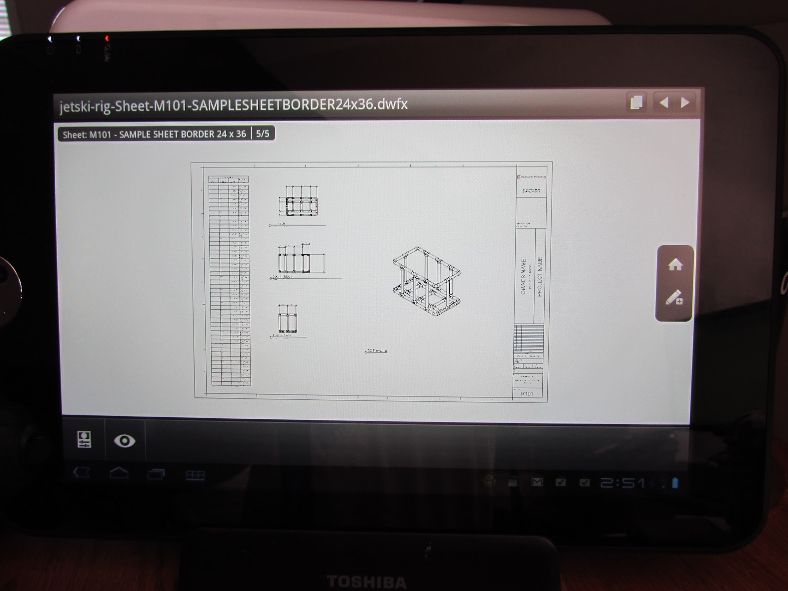
First up - design a cooler/rod holder rig. Being a Sunday afternoon with no NASCAR, I came up with a little model in Revit MEP 2012, that used the default PVC pipe fittings:
That's where I found a flaw in the default fittings - while the elbow has the hub connection inside of the fitting, the tee's connection is on the face. Subsequently, I have downloaded the latest version of Charlotte Pipe's Revit PVC fittings, for the rest of my users to enjoy (http://www.charlottepipe.com/Default.aspx?Page=RevitGroups gets you complete libraries - very quickly).
The error in the fittings created an error in my pipe cut lengths on the schedule I defined, so I had to sort of wing it to get the shape correct. We've purchased Berkley adjustable rod holders (of the clamp on variety - https://www.nssnc.com/shop/product/berkley-baarh45-45-rod-holder?ct=10%2C207&sb=brand from my buddies at Neuse sports Shop in Kinston, NC) to attach to the sides of the rig, so I should be able to pull two rods and a net with no issues.
Next up is the installation of a Humminbird 385CI Combo GPS/Fishing finder with Downscan Imaging - this one should be interesting, we're using a RAM mount in the cup holder next to the dash (never could figure out why that was there - the bottles never stay there at 70mph).
So we're in assembly mode - when I get all this put together, I'll add another post with pics for you to enjoy...
Who says BIM geeks never get out...!
Later - David B.
 |
| My toy... |
First up - design a cooler/rod holder rig. Being a Sunday afternoon with no NASCAR, I came up with a little model in Revit MEP 2012, that used the default PVC pipe fittings:
 |
| Schematic Design...it don't look exactly like this... |
The error in the fittings created an error in my pipe cut lengths on the schedule I defined, so I had to sort of wing it to get the shape correct. We've purchased Berkley adjustable rod holders (of the clamp on variety - https://www.nssnc.com/shop/product/berkley-baarh45-45-rod-holder?ct=10%2C207&sb=brand from my buddies at Neuse sports Shop in Kinston, NC) to attach to the sides of the rig, so I should be able to pull two rods and a net with no issues.
Next up is the installation of a Humminbird 385CI Combo GPS/Fishing finder with Downscan Imaging - this one should be interesting, we're using a RAM mount in the cup holder next to the dash (never could figure out why that was there - the bottles never stay there at 70mph).
So we're in assembly mode - when I get all this put together, I'll add another post with pics for you to enjoy...
Who says BIM geeks never get out...!
Later - David B.
Wednesday, April 25, 2012
Old Guard is becoming New Guard - App for Sweets!
No, we're not talking about candy. McGraw Hill, the publisher of the massive Sweets product specs catalog, has created an app for mobile devices - so you can browse through their catalogs - for free - on your iPhone, iPad, or Android tablet. I downloaded it to my Toshiba Android, and it's slick - just browse, and look under the latest version of CSI spec classifications.
Man, I used to keep a whole shelf of these things, but had to hire somebody with a dually to recycle those things. My tablet's a whole lot lighter...check it out at http://construction.com/sweets/apps/.
Thanks, McGraw Hill!
later - David B.
Man, I used to keep a whole shelf of these things, but had to hire somebody with a dually to recycle those things. My tablet's a whole lot lighter...check it out at http://construction.com/sweets/apps/.
Thanks, McGraw Hill!
later - David B.
Monday, April 23, 2012
AutoCAD MEP 2013 - Back with More...
I've had some pets that for whatever reason, just manage to keep hanging around, no matter what I feed them. We had a cat (which I never liked but for whatever reason, loved me) that lasted 22 years, and no matter how grouchy she was, you had to love her.
AutoCAD MEP is getting like that - it's the old comfortable show, that you just can't seem to get rid of. Autodesk is kind of funny about this - they're all into the flash of Revit, and the analytical applications like Vasari and Stimulus that they're so stoked about. But for what it's worth, more than half of Autodesk's sales are still about AutoCAD...and there's a lot of users that are comfortable with it.
So Autodesk re-soled this shoe and put in some new laces, and we're ready to run again. Here's my favorite new stuff:
- Annotation Symbol planes for Front and Left views - this may seem like a small thing, but getting the corrected schematic symbol to appear in section view as the one in top views is actually, uh, important. It's crazy, but AutoCAD MEP has this, while Revit MEP doesn't (in fact, if you rotate a valve in Revit MEP, the annotation symbol gets turned on its edge and you can't see it at all). So I can see the valve consistently in all views. I created an exercise for the CADLearning series that shows this in great detail but you can either draw the linework, or import a design block you've used for years. Either way, this is a great tool.
- MEP Connectors - these data tools snap to the end of a pipe, and then let you make a connection to a Civil 3D or Plant 3D pipe - and pick up the size, material and system. One more step to integration (again, this doesn't work with Revit MEP...but I'm hopin'...).
- Schedule table groups make sorting the data a lot simpler - and gives you the ability to make your schedule's appearance really pop. I had always liked Revit's ability to group items, but this adds more for the ACAD MEP user - you can override the format by group, do group subtotals (and override their format),change orientation by group, indent...it just makes it all smoother.
- Autodesk systems and parts have really be dependent on Layer Keys for years, all the way back to the Softdesk days...but some users just like having their layers in their drawing when they start. Now that you can the layer directly instead of the key, it makes the customization a little simpler.
- The global replace fittings tool is nice - you don't have to pick items like elbows and tees, and worry about the connection getting broken. Being able to change them from elbows to tees (and back again) is even faster than the grip editing tool.
- With Duct Fittings, the radius is now controlled by the inner arc on reducing fittings - so now it looks and models more accurately than in the past.
- The Inclusion of the Fusion - man, I love this tool, for one simple feature. Use it to open an SAT, STL, IPT, etc. file - then use Save As to create a 3D DWG - and now it doesn't matter what the equipment manufacturer used to create their part. By getting the exact part used into the model, it makes the whole lifecycle part of BIM practical. And it comes with all of the BIM packages - both AutoCAD MEP and Revit MEP this year...man, I can't say thank you enough for making this easier. Sure, big files are still a problem, but we all have Windows 7, 64-bit OS, and lots of RAM....right?
You know, there are some days that I wish I was still running AutoCAD MEP all the time...and the 2013 release is making me jealous....but I do have an updated template available - you can get it around AU later this year...
later - David B.
Revit MEP 2013 - New Stuff, My Spin...
Last year, I was working to be the first one out of the gate...but this year, I decided to sit back and watch the free-for-all...I've got a lot of burning questions, now that we have a pretty good bunch of projects running in Revit MEP 2012 - which was a huge improvement over 2011, but still had some holes.
For the packages, I'm running Ultimate, so I'm really up for the infrastructure modeling - can't wait to see what this is going to offer for our site based work. Hope I'm not dreaming too much about this one. Otherwise, I like having one package, where all I need to do is turn on and off the panels I need...nice...
First MEP feature - Autodesk rearranged some of the settings for duct and pipe preferences, moving them from the MEP settings menu to the new routing preferences tool in piping types (aka: AutoCAD MEP routing preferences). I don't mind the move, so the sizes and segment settings are actually part of the pipe tool. The segments, while a nice add, aren't something we'll use much of due to the nature of water and wastewater projects, but for HVAC systems that combine both threaded and flanged systems (for example), this is a good tool to have. You can also still edit the segments under the MEP settings tool.
A good note is that centerlines are now available on connecting geometry such as pipe and duct - this answers a request we've been getting - minor, but needed.
It's the little things that count - now, the double click on the wheel of the mouse gets you a Zoom to fit - about time!
If you're using Revit MEP to size duct, you're going to be happier. This is lot easier now that the version 5 of the ASHRAE Duct Fitting database is part of the program. The user has to still pick the table in some cases (especially if a project from an older release is opened in 2013), but at least the analysis can be completed with better results.
Speaking of duct sizing, you can do a lot more with pressure calcs. Autodesk worked in two areas - calculating flow and pressure separately based on subsegments, and fixing the ability to calculate sizes when taps are used instead of tees. You can also produce a pressure loss report for a piping system, and pass it on to your engineers - make sure your system is well formed and connected, since you can get incorrect results if items just "look" connected.
I'm also real curious how the materials are going to play out. Dan Stine has written a great piece explaining the materials, ( http://www.aecbytes.com/tipsandtricks/2012/issue61-revit.html ) but the part I'm really interested in is the thermal properties of materials - how well will this translate into the heating and cooling load analysis, etc., especially since we're still using Trace (I'm not sure how well any of the older applications will support the import of the material settings - but is it going to work with Vasari?) Will a ductile iron metal material include the right properties, so any heat gain/loss from items that are in direct sunlight be taken into account for the heat load of a room? I'm not sure yet what the impact will be, but at least I'm interested...
Parts and Assemblies were new in 2012, but we haven't touched them...yet. My thought here is to look at how our equipment families go together - should the saddles for a tank be included in the family, but listed as a separate part - so it can be isolated for construction sequencing? Heck, I'm still having a hard time getting all the staff to do the modeling right. Most are on board, but do we really want our engineers breaking it down for the contractor? Are we getting paid enough money to add this feature? I think this will be driven more by the owner for MEP items than for architecture...
Key platform items I'm happy about (for more detail, check out David Light's column - http://autodesk-revit.blogspot.com.au/2012/03/what-new-in-autodesk-revit-2013.html):
- View templates now can update views where the view template was applied, when the view template is changed;
- Being able to apply a view template when you create a view;
- Editing requests are now answer with a direct click - that's a real time saver, makes it easier to not have to step out of what you're doing to grant or deny a request;
- Diameter dimensions - 'nuff said...
So for the MEP user, putting everything into one platform will be of some help. Platform improvements are always good. We're still in the stage of getting the users on the same plane of modeling, and getting them at least to the point of defining systems correctly this year. Upgrading won't be a major headache (except in regard to the segments feature), so that's a plus...but overall, this release is about setting the stage for better analysis of your model. There are still some items that need to be addressed, but getting more out of the model is critical for future users, so we're off to a good start.
Next up - AutoCAD MEP 2013 review...the old man's still got it...
later - David B.
Back from a short Hiatus...
Been extraordinarily busy the past several weeks. First news - the AutoCAD MEP 2013 CADLearning series (www.cadlearning.com) is in the can, and the guys at 4D Technologies are editing and cleaning it up as we speak. Look for some new and updated lessons this year. My favorite new feature in ACAD MEP 2013 is the ability to add schematic annotation symbols to front and left views of parts (specifly valves), so you can actually see the schematic symbol when you cut a section or view from a section. Now, if we can just get this behavior in Revit MEP (hint, hint...).
Next up - Design Review 2013 - looking at about 30 new lessons to help out all those engineers, architects and designers that we don't want touching our BIM models or documents...
thanks! David B.
Next up - Design Review 2013 - looking at about 30 new lessons to help out all those engineers, architects and designers that we don't want touching our BIM models or documents...
thanks! David B.
Tuesday, March 6, 2012
Revit Walls/Structural Walls/Rooms and Spaces...from the MEP Perspective
Now that we're getting deeper into Revit on our projects, we find ourselves in an interesting situation. The question is, who owns the walls? And why does it matter to the MEP user?
Our structure is pretty simple - we break projects up into 3 categories - architectural, structural and MEP/Process (yes, on most smaller jobs, these two are in the same project - the benefits far outweigh the file size issues up to about 150mb). Water projects are a little different than typical building jobs - the process drives the building, instead of the other way around.
Initially we started by saying, the architect owns the non-structural wall, and the structural engineer owns the structural walls. We did our first project this way (and we also let them own their own levels). This didn't work out too well for a couple of reasons. Not keeping the levels all in the architectural model (as architectural levels) cause MEP views to work incorrectly, when copy/monitored into a project. One of the impacts was on the space creation - it didn't like how the structural wall was defined, and caused a variety of areas. Both architectural and structural had levels at the same elevation as well, and this cause a lot of headaches on the MEP side.
Another issue came up when the architect created part of the wall for a room as architectural walls, and the structural engineer made the rest. Even with the structural model linked in and set to be room bounding, a couple of rooms never recognized the structural wall as a valid boundary, if the items are not at the same level or following the same bounding surface area. For example - if a structural user alters a structural wall, to move it to a different level or change the top/bottom constraint, the room and space fail. If the structural wall starts on a different elevation than the architectural wall (regardless of how it's defined, top to bottom or bottom to top), then the room and space may fail.
So here's a couple of ways to look at it. If an area of a building is meant to be occupied - whether it's by people, process fluids or equipment, etc. - then the walls that define the closed boundary should be defined as architectural. This way, regardless of whether they really are structural or not, a room can be properly defined for the area. The space association with room is the driving factor here - in order for a space to correctly track area electrical, HVAC and other power loads, it's got to have a good closed boundary. If the room works, the space will work too. You can always change the properties of the wall in the architectural model to be structural and load bearing, if that's the intent. Once the primary walls are defined, the structural model can copy monitor the walls, and edit the copies as needed to perform their structural layout and analysis.
Anything that's not enclosing an occupied area can be either a structural wall or non-structural, but my preference is that it be defined in the structural model - my thinking is that this applies to foundation walls, footings, etc. that are strictly there for support.
You can always link in structural models, set them to be room bounding, and place rooms where a combination of both structural and non-structural exist - just be aware that changes to constraining levels may cause you to have to rebuild the rooms, and subsequently, the spaces, in your project.
Hope this makes sense - let me know how you're doing it in your projects.
Thanks - David B.
Subscribe to:
Posts (Atom)