This will be my eighth (I believe) AU...but I'm nowhere close to some of the great instructors and leaders that have made this event the best anywhere for its software.
Shaan Hurley is one of these guys - and he's a great historian, too. A while back, he put together the AutoCAD timeline - now he's add the AU timeline. Check it out:
http://autodesk.blogs.com/between_the_lines/2011/07/autodesk-university-history.html
My first year, I got to be a lab assistant for Matt Dillon and Randy Burnette and caught the bug - the next year, I did my first class on my own, titled Interference? Verify and Analyze This, about checking for interferences in a project. And during the class, I tripped over the legs to the screen - twice...guess I didn't check for that interference first!
This year, I've got three labs - the two on Revit MEP 2012 filled up quickly, so as usual there will be a wait - but there's still a little room in my AutoCAD MEP lab (yes, I still love that product). And the annual tips and tricks class on Revit MEP (Supercharge your Revit MEP 2012) is approaching 200 - so let's get that one over the top!
What was your first year, and what do you remember the most?
Later - David B.
Monday, October 31, 2011
Thursday, October 27, 2011
Transitioning to BIM - A Guide for MEP Firms
Autodesk has published a whitepaper, Transitioning to BIM - A Guide for MEP Firms, that was written by Norb Howell and myself - it describes how our implementation has been progressing, and offers suggestions to those that are looking to implement BIM in their firm. Read it when you get the chance, and let me know what you think!
http://images.autodesk.com/adsk/files/transition_to_revit_mep_whitepaper_final.pdf
Thanks to Autodesk for initiating this, and to the entire design team at Gannett Fleming that is making this work everyday.
Later - David B.
http://images.autodesk.com/adsk/files/transition_to_revit_mep_whitepaper_final.pdf
Thanks to Autodesk for initiating this, and to the entire design team at Gannett Fleming that is making this work everyday.
Later - David B.
Tuesday, October 25, 2011
Working in Civil 3D - From Revit to the Site Plan
Brett Settles from Hagermann added a post on the Revit Community blog (you have to sign up to read it) that takes the Revit model the other way (form my previous post). Check out his post here:
http://www.revitcommunity.com/feature_full.php?read=1&cpfeatureid=62530&page=all
Nice!
http://www.revitcommunity.com/feature_full.php?read=1&cpfeatureid=62530&page=all
Nice!
LOONNNNGGGG Datum Levels - Use Scope Boxes to Limit!
We had a problem where we had imported some sites that were pretty spread out - so when my using maximized his levels to 3D extents, they went WAAAAY off in space. After a half hour of stretching the grips, it started to get pretty frustrating, so I did what I should always be doing - go to the Autodesk support discussion groups (support.autodesk.com). I found this solution from Cliff B. Collins, a Registered Architect/BIM Manager at Thalden Boyd Emery Architects in St. Louis, MO .....on the Revit Architecture page...go figure, an MEP guy looking to the architect page for help (thanks and kudos to Cliff, BTW).
He recommending using scope boxes to limit the extents of the datum levels. You'll need to do this in the file that the original levels are placed (in our case, the architectural model) From the view tab, pick the scope box tool:
 Next, pick two points in a plan view around the building you want to restrict the levels to:
 Once the box is placed, you can stretch and rotate the boundaries as needed. Before you switch to an elevation or section view, you need to make sure the scope box is visible. While it's still selected, go to the properties and pick the Edit tool for Views Visible:


Now we can all play nice - David B.
He recommending using scope boxes to limit the extents of the datum levels. You'll need to do this in the file that the original levels are placed (in our case, the architectural model) From the view tab, pick the scope box tool:


Change the elevations from invisible to visible in the view you want to use (I'm picking South - Mech as the override).
Go to that view. You'll see the scope box, and can edit the boundary from here as well. Pick the level you want to pull back to the scope box - when the level is selected, go to Properties, and change to the Scope Box 1 as the extents.

Now the level matches the scope box boundary. This tool comes in handy when you have more than one building on a site, and want to just show the levels relative to the specific structures. If you have more than one structure, name the scope box after the structure so it's clear. When the MEP engineers get your architectural model this way, we'll promise to love you forever...until you ask us to make some other flaky change...
Working with Sites in Revit...and avoiding Pain!
This one's a pain no matter what you do...it's caused by a limit in Revit, which has a 20 mile radius of accuracy away from a project base point. If you are trying to bring in site files, and the site files are defined at their real-world northing/easting coordinates, you have to move the site to Revit. It's not the other way around, so here's what you need to do.
First, if you're in Civil 3D our AutoCAD, make a duplicate of your site model drawing. In the duplicate, turn on, thaw and unlock any layers you want to include or manipulate. We need to have the contours, TIN, surface, existing and proposed structures at the least.
You're not going to rotate the site (we'll take care of this in Revit model by rotating a view). You're also not going to flatten anything - make sure the surface, existing building layouts, etc. are at their 3D elevation (BTW - if you're a plain AutoCAD user, and you're flattening sites to have no elevation, you're not allowed to play in this park).
Second, you're going to have move everything (yes everything) to 0,0 (not 0,0,0). Use a known point - like the corner of a proposed building, corner of a lot, etc. so that the model is within 20 miles of 0,0. That's why you want to open up all the layers - so you don't leave anything stranded, and out in spaces. One of our users adds a location marker that he uses as a reference, so he knows where he's coming from and going to.
Third, if needed, run the export to AutoCAD command from the Civil 3D application menu - this dumbs everything down to 3D models and plines - this converts it to non-Civil 3D objects while maintaining elevation. You only do this if the geometry doesn't come into the model as expected.
Another option is to create a rectangle around your site, and use the AutoCAD trim command to get rid off long linework that runs out into space - you're doing this if you have long lot lines, roadway profiles, etc. Keep it focused on the area of the site you're working on,and keep the model small.
Once you do this, you can use the Link CAD tool to bring in the file as a reference - don't import it, as these still get changed over the course of a project. We're mainly doing this for sites that have more than one structure or building - if they're small, it makes it easier to keep all items relative. It also helps to do your project this way when you have a lot of connecting components in a model, and are running pipe, etc. between the buildings - or connecting power circuits to panels in remote locations.
The CAD file will come in at elevation - so it will help you add your levels at the correct relative elevation to the site.
I'd include images, but since a lot of these projects I'd use are active, I need to refrain...but hopefully this helps you to streamline your workflow.
Monday, October 17, 2011
Getting to the Penpoint in Revit MEP
Got a call from one of my techs today saying he didn't like the way the architectural and structural backgrounds look in the MEP electrical/mechanical disciplines, when he printed them out.
I love the way the background is already lightened, but occasionally (ok, all the time), I gotta tweak the defaults to keep the higher ups happy. Two ways to do this.
 1 - In the Print dialog, go to Setup - change the default for Replace Halftone with thin lines. One note - penweight settings for anything that was set to halftone in the VG dialog were disabled when this option is checked, so expect them to be thin.
2. Leave the print setup options - but go to object styles. Make sure you turn on the option for showing all disciplines - for each architectural or structural object that you want to make thicker, change the lineweight for projection to a heavier pen.
A couple of other plotting tips -
later - David B.
I love the way the background is already lightened, but occasionally (ok, all the time), I gotta tweak the defaults to keep the higher ups happy. Two ways to do this.

2. Leave the print setup options - but go to object styles. Make sure you turn on the option for showing all disciplines - for each architectural or structural object that you want to make thicker, change the lineweight for projection to a heavier pen.
A couple of other plotting tips -
- Set the object style display options to coarse in MEP views for architectural objects such as walls - that turns off the patterns.
- Just want to turn off the patterns? Go to the VG settings (I also do this in my view template), under Projection/Surface > Patterns, uncheck Visible for any patterns in the walls - that leaves the boundaries but turns off the hatch.
later - David B.
Tuesday, October 4, 2011
Avoiding Conflicts - Duct and Pipe Routing Tip for Revit MEP
Got a situation where you have ducts or pipe at the same elevation? The fix is easy -
Start by drawing your ducts as a single run:
 Add a section and then change to the view:
 Use the split command (on the modify panel to break the duct into three pieces (check the delete inner segment option) Note: the program will add a union if the duct type has it included – if it does, delete the unions):
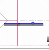
 Move the middle section to the elevation you want – and if you want to slope the duct or pipe, stretch the ends back to give yourself a little room:
 Right click on the grip on the top duct, and then just draw the duct down to the lower duct – you can draw it at any angle as needed:
 Once the layout is done, you can edit by changing the elevation of the flat runs of duct, or use the grips on the fittings to move.

 You can add or remove control points, use the grips in the preview to move the connections, etc. as needed – when you’re ready, pick finish:

Start by drawing your ducts as a single run:


You can also use Routing Solutions to create a connection between any two ducts:


So the final result is that you avoid a conflict – and it only takes a few seconds in section view to fix.
Side note – if you’re using AutoCAD MEP, you can do the same thing – just make sure you check your duct routing options, and turn off the Automatic Create New Riser at elevation change option, and you can create sloped duct or pipe!
Get routing!
Subscribe to:
Posts (Atom)